Plan Dimensions
Hello All,
I am reviewing plans from the drafting company and I wondering if I can get some clarification from this group.
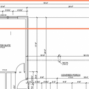
The plans have dimensions that indicate windows, door and there respective centerlines (see atch’d image).
I have a cantilevered bottom plate for exterior walls (to assist with partially covering the 2″ xps under the slab). That makes the foundation wider (in about 2″ increments) in several locations — to allow the rooms to keep their respective sizes. So, I am thinking that the foundation’s overall width is larger than the floor-plan’s overall width.
Are the dimensions on the floor plan derived from the outer edge of the foundation or the outer edge of the wall (see same atch’d image)? And won’t the Foundation plan show the larger width in various locations?
Thanks.
GBA Detail Library
A collection of one thousand construction details organized by climate and house part


Replies
Typically residential floor plan dimensions would be face of stud. If the house is simple, the contractor will calculate the adjustments to determine the foundation dimensions. On complex projects I (as an architect), will provide a separate dimensioned foundation plan.
Thanks Dan - I think our build is pretty 'simple', in that there is only 8 pages to the construction docs/plans. We do have a couple of 'outside of the norm' type details; like the cantilevered bottom plates and exterior insulation. There is a page dedicated to 'Foundation' so, that will save the subs from doing too much math I suppose.
Like Dan, I dimension to the face of framing, but that's not a universal standard--I know architects and designers in other parts of the US who insist on dimensioning to the face of sheathing, or to the face of all finishes. Or they may dimension to the center of the wall instead of the face. In short, there should be a note on the plans about the dimensioning system, and if there isn't, I would ask the person who provided the plans.
"who insist on dimensioning to the face of sheathing, or to the face of all finishes."
I've bumped into that a couple of times. It shows a fundamental lack of understanding of how houses get built. The basic shape comes from the framing, and the last thing framers need is having to stop and do calculations on site.
Using similar logic, I always make sure not to leave a gap in my dimension lines. I know some designers like to do it to show that is the least important one and can take up any small slack, but it leaves the contractor guessing as to the length of the plates necessary, and they typically just figure it themselves - again inviting errors.
Michael - you make a good point about the presence of a note indicating the faces used for the measurements. I'll just added a task to check that is noted.
Thanks
idahobuild,
It's usually one of the general notes on the first page along with "Do not scale drawings", and others about reporting any discrepancies to the designer before proceeding with construction, etc.