Can HVAC unit properly sized for capacity deliver too few CFMs for load? How to tell?
I’ve been conducting a manual J, S and D by myself for my house and I’ve hit a wall. (I went with a firm for an initial design, but wanted to continue iterating on the designs and they’ve been difficult to partner with in that way).
My problem: I cannot tell if my design would be delivering too few CFMs for my needed loads, and, if so, why. I can’t even tell if this is a valid question.
***
I designed a ducted, concealed heat pump system—with trunks, supply runs and all—that satisfies TEL (total equivalent length needs) and pressure drop requirements.
I used the http://hvac.betterbuiltnw.com Manual J + S software recommended on this site and also the ACCA manual D speedsheet for calculating duct sizes: https://www.acca.org/viewdocument/acca-speed-sheet-for-manual-d. This was also a very helpful resource: https://hvacrschool.com/manual-d-speedsheet-walkthrough/
The loads for this zone are:
– Heating load: 21,500 BTU
– Total cooling load = 15,900 BTU (sensible load = 12,100 BTU; latent load = 3,800 BTU)
(Note: BetterBuiltNW does not output total CFM needs in its Manual J calcs. I’m not sure other software does)
I’m designing around this Fujitsu concealed ducted heat pump unit:
Max CFM: 554
Outdoor Unit Model #⁺: AOU18RLFC
Indoor Model #⁺: ARU18RLF
Rated Heating Capacity (Btu/h) @47℉⁺: 21,600
Rated Cooling Capacity (Btu/h) @95℉⁺: 18,000
Full ASHP specs: https://ashp.neep.org/#!/product/32101/10/21500/85/15900/0/11940/744865/1
This unit should work for these load demands as discussed here: https://www.greenbuildingadvisor.com/question/how-to-size-heat-pumps-for-cold-winters-and-hot-and-humid-summers
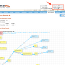
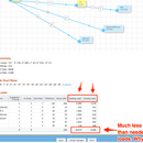
But, and I can’t tell if this is a bug in its software, BetterBuiltNW is telling me that this ducted configuration and its CFM output per supply register in aggregate will output heating and cooling loads that are much lower than my design needs (see the attached images).
Why is that? Does this actually suggest that the system won’t satisfy my design loads or is this a bug? Is there an equation that calculates heating loads from outputted CFM (so I can reverse engineer what BetterBuiltNW is outputting in that table)?
I’m confused by this because a Manual D seems to determine the CFM output at each register by taking the total CFM output of the blower and distributing it by room according to the same distribution of the total heating load across all rooms. And if a unit’s heating capacity is large enough to satisfy the total heating load, then a ducting system with sound TEL, duct sizing and pressure drop will move that capacity proportionally just fine. The core unknown for me is whether a system has “enough total CFM”, but I have not figured out how one calculates that. And it seems that CFM tends to positively scale with total capacity (for example: you won’t find a 800 CFM unit with the same capacity as the unit above; in other words, if I want more CFM, I would get a bigger capacity unit, but then I’d wind up with an oversized unit).
What am I missing here?
-Luke
GBA Detail Library
A collection of one thousand construction details organized by climate and house part


Replies
It looks like the calculation is returning the correct CFM.
Heat delivered by air is equal to the CFM times the temperature difference between the air and the room times 1.08. To get 21,600 BTU/hr with 554 CFM you need a temperature difference of 36F. It looks like the calculation is using a difference of 31F. Do you have any idea where they're getting that number from?
The control algorithm of heat pumps tends to vary both the CFM and coil temp to maintain setpoint. If the setpoint is not being met the both will be increased.
Note that with ducted heat pump heads, part of the commissioning process is to set the unit up to match the design ESP of the connected ductwork (SP mod variable can be 09 for high/ normal / 00 for low. It will run the fan on a different RPM curve to get the target flows. So as long as the fan is capable of moving the correct air at high flow settings it will likely be ok (assuming properly designed and balanced ductwork). You'll need to dig into the submittal data to see fan performance at difference ESPs.
I've run into the scenario where unit backs off (mostly point source single zone heat pumps) prematurely, due to not great space sensor placement (setpoint appears to be satisfied). This would be an issue regardless of the heat source, but it's aggravated by a modulating source though because it needs to see a load to really ramp up, versus an old school furnace that cycles on/off at high capacity.
It appears that it can move more than 540cfm if your ESP is less than 0.36in.WG.
https://images.greenbuildingadvisor.com/app/uploads/2018/08/30173846/ARU18RLF.pdf
That's all true, but it doesn't answer the question he's asking. Which is, why does the modeling software not show the rated BTU's but does show the rated CFM?
The answer lies in what assumptions the modeling software is using.
Thanks, all. I tried to trace the source of that 31F and couldn't find it. I have no idea where that's coming from. Maybe that's a bug with http://hvac.betterbuiltnw.com? I'll keep looking.
Reflecting on your original response...
"Heat delivered by air is equal to the CFM times the temperature difference between the air and the room times 1.08. To get 21,600 BTU/hr with 554 CFM you need a temperature difference of 36F"...
I know we're essentially debugging here, but I'm wondering if this calculation is pertinent at all to system selection. Let's say we're at 10F, my design temp, in which I need 21,600 BTU/hr. That would imply that the air temperature coming out of the unit must be at least 46F to deliver on that if it produces at most 554 CFM, right? If it can extract that much heat from the cold outside air, then that seems feasible.
I guess I'm struggling with how I would use this information to select a unit, or if I need to at all.
It's the temperature change inside. To get 21,600 BTU at 554 CFM, the air coming out of the unit on the inside has to be 36F above indoor air temperature. So if it's 72F inside the air coming out has to be at 108F.
The outdoor unit is totally separate, it has a higher volume but low static fan. The manufacturer publishes a max capacity at various OATs. Just ensure you happy with the capacity at your design condition. The outdoor unit fan can move up to about 1400cfm to keep the temp delta (and pressures) within a reasonable range.
This may be helpful or not but the old school HVAC equipment always came with a blower sized to deliver 400 CMFs per ton of capacity.
If you move more than 400CFMs you reduce the laten heat capacity while increasing the sensible capacity IE you remove less moisture from the air. If you move too little air across the coil the surface of the coil may fall below freezing and turn into an ice ball blocking more air movement making the ice ball bigger. At some point liquid refringent get back to the compressor and thing get ugly.
In general, the ductwork tended to be undersized and the equipment struggle because it moved less air than it should.
Walta
Here's a good read on duct sizing. I'd check out all 5 parts.
https://www.energyvanguard.com/blog/basic-principles-duct-design
Also anecdotally, I was looking at a Daikin Aurora unit yesterday, the Cx process specified confirming a 36degF temperature delta in heating.
When in doubt give yourself some headroom you can always balance it down, but making ductwork less restrictive is a redo. It might less you run at a quieter fan fan setting too adding comfort and consuming less fan energy.