
More Building Matters


In 2023, New Jersey, where I am an architect, adopted the 2021 International Building Code (IBC) and the 2021 International Residential Code (IRC). Along with the new codes came requirements for higher insulation values across the entire state. Previously, the 2018 codes could be satisfied by a 2×6 wall with R-20 stud-cavity insulation, or a 2×4 wall with R-13 stud-cavity insulation and a layer of R-5 continuous insulation. Unsurprisingly, the majority of designers and builders chose the simple 2×6 wall and avoided the continuous insulation.
But under 2021 code requirements, the whole state must provide R-20 + R-5 continuous, or R-13 + R-10 continuous; or a single-cavity wall of R-30, or a single layer of R-20 continuous. A similar situation is about to emerge in Pennsylvania, where the 2021 codes will soon be adopted. And similar changes will come to other states in climate zones 4 and 5, when moving from 2018 to 2021 IRC requirements.
A good thing, right?
It’s good model building codes are making people build higher performing assemblies. We all know the GBA community is often focused on outperforming code minimums. But we also know the majority of buildings are made to do no better than meet codes.
This is my area of concern—for the majority of designers and builders going for code-compliance only. They appear unprepared for these impending code changes.
Weekly Newsletter
Get building science and energy efficiency advice, plus special offers, in your inbox.
Over the past year, every builder I discussed the code update with was unaware of the change in insulation requirements; none had noticed the higher-insulation assemblies in my drawings, and in some cases, they were about to mis-bid their work.
After I called their attention to the new requirements, they later told me that architects of other projects they were pricing did not have the new requirements reflected in their projects. When I reached out to architects I know in NJ, I found that many of them were also unaware of the change in insulation requirements. I was convinced that this lack of knowledge was widespread, and the implications serious.
What are the implications?
Because the code’s implication is that the continuous insulation layer must be at the exterior, I was very concerned. Here I was talking to designers and builders statewide who were clearly unprepared to suddenly be thrown into detailing flashings for water management with an exterior layer of insulation that they had little experience with.
Continuous exterior insulation (CEI) can be more complex, and water-tight detailing more challenging. Where is your drainage plane now? Where should windows be placed? If windows mount to the sheathing, how do you trim the gap between cladding and window frame? If you use a projected sub-frame, how do you flash projecting frames to prevent water entry?
Are we setting the stage for statewide construction errors? Why are we taking on this complexity? Is this really what the IRC requires?
Language specificity
Some may argue the code does not require the continuous layer to be at the exterior—that the IRC does not explicitly call for exterior-side insulation. However, interior-side continuous insulation is understood to be impractical, as it interferes with the mounting of interior finishes and fit-out. So, the de facto reading of the IRC is a requirement for CEI.
This interpretation is clearly the understanding of the industry at large, where we see a flood of products aimed squarely at CEI. Sheathings with laminated insulation, rigid insulation with laminated air and water barrier, dense and rigid batts—all are being touted as exterior insulation solutions. Companies are investing millions developing and promoting new products. They clearly see a great market opportunity in the CEI-only interpretation of the IRC.
In this context of tremendous market pressure toward CEI, we have to remember that the code does not require this configuration, and that designers and builders facing the transition to higher performing assemblies may be better served by a compliant wall that does not force them into using and detailing complex exterior insulation for the first time.
An alternative wall assembly
So with my colleagues Michael Maines* and Hans Breaux—both are located in Maine and have been working under the R-20 + R-5 continuous requirement for many years—we have written a white paper to document compliance of a greatly simplified wall assembly consisting of R-20 + R-6 “cross-furred continuous insulation” located at the interior side of the wall.
What is cross-furred insulation? Let’s start with the 2×6 R-20 wall that NJ designers and builders have been using for years. This has been the default for stud construction because the only alternative was a 2×4 wall with R-5 continuous, and unsurprisingly—and without any coaching—designers and builders avoided building the alternative assembly.
At the exterior of the cross-furred wall, it is the same as it ever was. If you favored rainscreen cladding, you can continue with your reliable practices there. If you installed vinyl siding over Tyvek, you don’t have to make any changes.
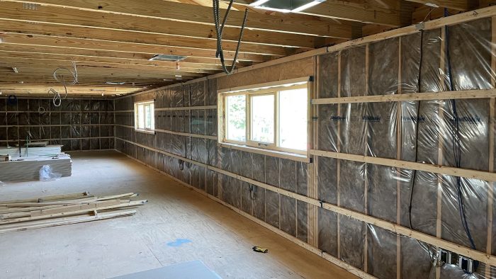
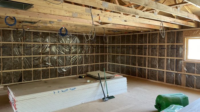
At the interior side you are going to add just two new elements: horizontal 2×2 cross-furring at 24 in. o.c. vertically, moving the drywall inward and increasing the overall wall thickness from 6-1/2 in. to an even 8 in. Inside this newly formed cavity we insulate with 1-1/2-in. R-6 batts. Our vapor control membrane— whether kraft-faced vapor retarder, or “smart” membrane—remains at the inside of the main stud cavity.
The new work—installing furring strips and batts—requires no new techniques, no new skills, no new trades. It’s simple, it’s fast, and it’s effective. The cross-furring does create a small thermal bridge where the furring is attached to the main studs, it is completely overcome by the increase from R-5 to R-6 for the continuous insulation. Performance is marginally better than the IRC-described assembly, for less work, less time, and less risk to inexperienced builders.
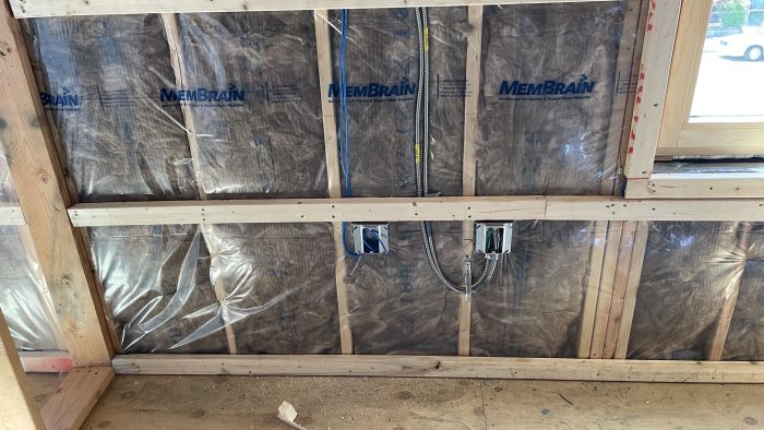
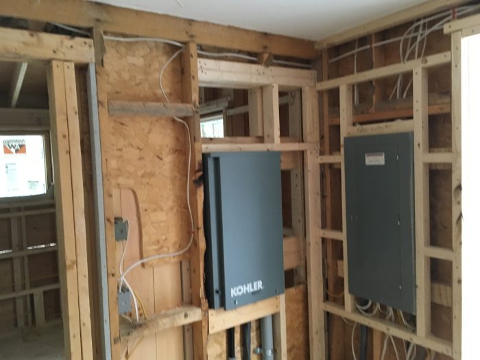
While the service cavity is simple and does not demand new skills from trades, it does change the approach to electrical wiring on these exterior walls. At these locations it is necessary to mount devices in 4x4x1.5 square boxes rather than conventional deep-wall boxes. This does not present any great difficulties as the 4×4 boxes typically have a greater interior volume than standard single-gang boxes. When 4×4 boxes are used with a device plate reducer cover matching the depth of the drywall, these boxes can easily accommodate bulky devices such as dimmers or GFI receptacles. Wires are routed at the back of the service cavity, and covered by the R-6 insulation, and where running vertically they pass behind the horizontal furring member providing the code-required depth of cover along drywall screwing locations. This small change to electrical work at exterior walls takes no more time or cost than wiring in a conventional R-20 only wall.
A variation
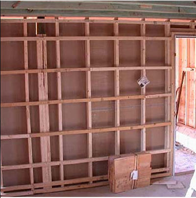
The photos below show the cross furring in place before the main stud cavity has been insulated, which can be problematic, unless the plan is for blown-in insulation, as was the case here. Typically, the main stud cavity is insulated, and the vapor control sheeting installed before the cross furring goes up, as shown in the photos above.

White paper highlights
In the white paper, we make the argument that this new designation: R-20 + R-6 fci (furred continuous insulation) should be presented in the IRC side by side with the current R-20 + R-5 ci designations, to make clear that this assembly is compliant and available to builders.
Without IRC–supported compliant status, designers and builders using this wall assembly are left having to prove compliance to local code officials each time they seek a permit—a redundant and costly burden. To ease this pain point, we have provided simple instructions on how to establish compliance through ResCheck in the Appendix of the white paper. (The paper also includes technical background documenting the compliance and the increased performance of cross-furred walls.)
In the meantime, the goal is to spread this information widely to try to offset the situation in states transitioning to newer versions of the IRC. Putting this information in the hands of designers and builders could avoid a lot of struggling with new techniques and related construction errors. The best way to share this would be to have the new R-20 + R-6 fci appear in the Minimum R-Value tables in the code. However, such a code change is a multi-year process, which would be way too late for builders in NJ and elsewhere.
Most states edit the model codes when adopting them, so there is an opportunity for individual states to insert this new designation into their state codes. But the state code adoption process is also a multi-year venture.
More immediate is that most state code departments publish newsletters and other media communications sent to local code officials. Sharing this information through these state channels could help reach every local code official.
Beyond these official channels, there are industry communities, such as GBA. If you agree that it will be useful for builders and designers to avail themselves of this code-compliant alternative wall assembly, please share this through your network.
*Mike shared this anecdotal note in an email:
It’s sometimes called a “Mooney Wall,” thanks to an old Break Time Forum thread, where the idea was first presented. Builders Mike Smith and Tim Mooney had long conversations about it 20+ years ago, and they flipped a coin to decide whose name they would use to identify the wall. Many people now know it as the Mooney Wall. Although it pre-existed them, I credit them for bringing the assembly into prominence. (For photos of cross-strapped walls that Mike Smith built, go to builditsolar.com.)
____________________________________________________________________
Gregory La Vardera is an architect; co-founder of Bygghouse, WarmFörm, a frost-protected slab system. Photos courtesy Michael Maines, except where noted.


33 Comments
Good-on-Ya! as they say in Australia. It's long past time to find
a practical way to put the rigid layer interior rather than exterior.
"Practical" meaning inexpensive and code compliant. Good-on-Ya!
Horizontal interior strapping and insulation - this is precisely the solution I came up with for houses in Zones 6 & 7. It's great to see it here. As far as proving its code compliance, I've got this simple excel spreadsheet for calculating total wall U-value, to show compliance with IRC 2021 Table N1102.1.2.
The framing factor is based on 24" framing with insulated headers, and rim joist headers where possible.
The one drawback is that the need for having a vapor control layer between the studs and horizontal framing means that framers and insulation installers have to overlap. I've been wondering about the practicability of using Kraft faced R20 batts, which could, theoretically be installed after the horizontal framing is in place. It still seems like a hassle though. if it weren't necessary to have the vapor control layer at that face, then it might also be possible to dense pack cellulose into the entire assembly after all the framing, vertical and horizontal, has been done. Would this work if a smart membrane was installed after the dense pack goes in? That would put the vapor control layer at the innermost face of the insulation.
In practice the sequence of work when the membrane is at the main studs is not a problem. Rather than have an insulation sub return, they can leave the 1 1/2"batts and use other labor to install them after the rough-in inspections for electrical are done. That has been my experience on jobs with cross furred walls.
Yes that's Mike Smith's Mooney Wall - although he always used blown-in cellulose, and located the vapour-retarder on the interior face, which as JGSG say's makes the sequence of construction easier. Unless the membrane is also functioning as the air-barrier, I don't see any advantage to having it located on the interior face of the studs.
One small complication with the 2"x strapping is that you have to frame inside corners and the intersection between exterior and interior walls differently to provide backing.
Yes - the vapor control sheet is intended as the air-tight membrane. Locating here at the face of the stud, instead of behind the drywall, eliminates nearly all of the penetrations caused by electrical boxes, and greatly simplifies achieving air-tightness. Its much easier to work the membrane while standing on the floor deck, than on a ladder outside, particularly with a two story house.
Greg,
If it's also the primary air-barrier then having it protected behind the strapping makes a lot of sense. Identifying what constitutes the air control player on the drawings is important, as the membrane gets treated differently than if it were just for vapour control.
Have you considered using the taped sheathing as the primary air-barrier? That would eliminate air-sealing issues in the wall cavities and mean the membrane could be eliminated in some climates in favour of painted drywall.
Stepping back: This is a really useful initiative. Well done!
Malcolm, all these variations you mention, and others like blowing in all of the insulation. All these are possible and I would encourage them. For the purpose of the paper we wanted to stay to the lowest common denominator - It had to work with the insulation types and techniques that builders confronted with the new Code requirements are accustomed to installing, and estimating.
I always want to have the outside face as air-tight as possible, whether that's plain old tyvek or taped sheathing, because I want to prevent the possibility of getting bulk amounts of our humid summer air getting into the wall cavity and encountering cold interior surfaces. This is even more important when a builder is using kraft faced batts and is not making an effective air-tight membrane at the interior side of the main studs.
Thank you for this article!
A layer of interior furring and insulation has been a great way to add R-value, air sealing, and added services (particularly electrical) to existing walls. I've called these "innie-only" retrofits. But I also love the idea of developing an IRC-approved compliance pathway for new fci walls. You even have the three-letter acronym ready for the officials to adopt.
This is a great example of what's possible when experts know the science and have enough command of the variables to suggest smart and practical alternatives. Once something smart is adopted by the building code, everyone (smart or otherwise) benefits.
- Hydrothermal modeling and real-life installs are important to demonstrate that condensation won't be a problem on the inner face of the 2x6 stud (so it can be fully adopted by code)
- As one of the photos in the article shows, there can be a substantial amount of bridging area (furring and stud overlap area) at corners, windows, and interior wall penetrations. Again, I would advocate for some more testing to see if an additional 1 R-value on the fci assembly makes up for the more-continuous and more-thermal bridge-free cei assembly.
- Designers and installers need to have realistic expectations with vapor control sheets spanning over cavity openings - they make a lot of sense for high-performance wall assemblies and are becoming more common - but they are fussier than exterior membranes applied over solid sheathing. Someone on the construction team needs to be designated as the "gift wrapper" or the person responsible for installing, taping, and repairing the vapor control membrane through construction.
- Make sure your electrician is aware of this approach before they bid or accept the job - or you'll be arguing with them endlessly during rough-in
oldaltnew,
"Designers and installers need to have realistic expectations with vapor control sheets spanning over cavity openings... Someone on the construction team needs to be designated as the "gift wrapper" or the person responsible for installing, taping, and repairing the vapor control membrane through construction."
Unlike air-barriers, vapour-retarders do not need to be continuous or taped. Incidental tears or gaps do not affect their performance.
Malcolm, I was recently made aware of this (vapor control not needing to be airtight) from a Bldg Sci Corp article, I think, but wonder if this is less true when a house is quite leaky--if there's a pathway to deliver a lot of moisture to exterior sheathing from the inside? Do you have a good article to point to about this? Thanks, and thanks Gregory for this article
tomb-d,
The confusion is between air-barriers, and vapour-barriers or retarders. The vapour control layer's effectiveness is determined by the percentage of the surface covered (cover 90% of the wall and you have stopped 90% of the moisture moving though it). It's air barriers that need to be completely continuous to stop moisture laden air moving through them. So yes, leaky houses allow more moisture into walls, but that has to do with the continuity of the air-barrier, not the vapour control layers - which may or may not be the same material, or in the same place in a wall assembly.
It's an important distinction, not just for us to understand what is in play, but because it's one all building codes make. They have very different requirements for each, including what materials can be used, and their locations within assemblies.
Well-said, Malcolm. I find that the air control layer and vapor control layer are some of the most-often-confused elements, including among design and construction professionals.
Malcolm and Mike, that's not my confusion--we've been doing Phius buildings for years and we understand air control really well. As we've switched to double-stud walls with exterior air control and mid-wall vapor control (Intello), we detailed the vapor like air, in other words, probably more taped/sealed than we needed to be. But as oldaltnew says, we'd fine even with gaps because it's an airtight building. It's in our retrofits that aren't so airtight that I think the "don't worry about the tears and seams" of the vapor control can get more risky. Hence my asking if you knew an article that went into detail on this. I'll keep looking.
tomb_b,
I didn't mean to imply you didn't know the difference, just that we were all talking around different things because we we weren't clear on whether the vapour control layers were also acting as an air-barrier (see post #5 above). And when I explained the difference in a bit more detail than you turned out to need, it wasn't to be patronizing, it's because these threads are read by people with a variety of expertise, who may appreciate a fuller discussion.
No sane project manager would approach their GC and tell them shoddy installing of any material would be alright by them, but that's a very different question than whether an incomplete vapour control layer makes an appreciable contribution to moisture accumulation in walls - and again I think the answer to that is: Only if it is also acting as the air-barrier. So when you ask whether tears and gaps become risky in leaky houses, aren't you really asking: Should the vapour control layer be detailed as an air-barrier just in case? My answer would be: Of course the first thing you need to do in a leaky house is provide a good air-barrier, whether that's the vapour control layer of something else. If it is something else, I've never seen any evidence that an incomplete vapour control layer acting just in that capacity, makes an appreciable difference to the moisture accumulation in building assemblies.
Tomb, this may be a good substitute for an article: https://www.greenbuildingadvisor.com/article/air-barrier-or-vapor-barrier-building-science-podcast. There are many other discussions and articles here at GBA, and various papers on BSC's website. Watch out for older articles, as they are often superseded by newer articles that have more data supporting them.
Sure, if you can control air from the exterior, and if you can trust that layer alone, the interior vapor control layer can be spec'd as just a vapor retarder / smart vapor control layer. Even the finish on the gypsum wall board is going to contribute to the wall's vapor control profile. But I'll stand by my statement: someone needs to be responsible for ensuring proper installation and repairing damage during construction.
If I told my GC that "incidental tears or gaps" are fine, tears and gaps are exactly what I'll get.
Agreed, the difference between air barriers, vapor barriers, and vapor retarders are important to understand and illustrate to get the strategy right.
oldaltnew,
Much of this discussion could have been forestalled if the membrane had been labelled "air and vapour control layer".
but it's not an air control layer--that's exterior at the sheathing. I'm with you on this, oldaltnew, important to set expectations on the vapor control as well
tomb_d,
See Greg's post #5 above.
Seems like the low cost path of least resistance will be the 2x8 wall be it solid or engineered.
Walta
Washington State, where I work, adopted the 2021 codes recently. 2x8 walls aren’t a prescriptive option in WA, but I suspect that most jurisdictions will allow builders to do them anyways, or perhaps they’ll simply decline to enforce the CI requirements. It seems unlikely that smaller jurisdictions (basically anything outside of King County) will feel inclined to start forcing inexperienced builders to do CI.
Sounds like Washington edited the R30 wall out of their code adoption. I am curious - did they leave in the R20ci only option?
When +5ci was added to 2x4 walls, everybody here in NJ seemed to naturally jump to 2x6s. Walls of 2x6s were not completely unheard of - two story foyers and family rooms, and other grand gestures of the McMansion class of construction often called for 2x6 walls because of the height.
Somehow I don't think people are going to make the same leap to 2x8 walls. The cost of a stud vs a joist/rafter may not be less than the continuous insulation work. But we're going to find out - the market always settles on the least cost option.
Chelan certainly seems to be enforcing it, at least when permitting.
Interesting concept. The attached white paper makes a compelling case for adoption. This assembly, with additional variants, is discussed on Gregory La Vardera's site as the 'USA new wall'.
Questions:
1) What type of insulation is used for the 1.5 inch R6 batts in the service cavity? I don't recall seeing 1.5 inch batts. Is this actually Comfortboard, or...? Curiously, the furring in the photos looks like 2x3's nailed on the flat. This should work OK, maybe even provide improved nailing for drywall, but what about turning the 2x3 furring 'on edge'? It would require longer nails (or screws), but 2.5 inch batts are available in Comfortbatt (R10) and also fiberglass (R8), although both are sized for steel studs from what I can find.
2) If the vapor control membrane also serves as the principal air control layer, how is continuity maintained between floors? Joe Lstiburek lays out some options in BSI-084, Forty Years of Air Barriers. Is it one of these? Using taped sheathing sheathing as the primary air barrier might be more reliable, as others have noted above.
Typically you will find the 1 1/2" thick batts marketed as acoustic batts. These are usually cut from the same density batts as stud wall insulation, and while some manufacturers don't offer data on the R-value you can easily determine it by looking at the R per inch on like density products.
You could use the high density batts that Rockwool calls comfort board, but in this application the rigidness is actually not desirable as you want the batts to easily conform around any wire routed through this cavity.
The same challenges exist for this wall as any wall at the floor levels. Many possible solutions have been discussed elsewhere and were not the subject of the paper. If you are focused on digging deeper into ways to solve this I would recommend looking at the "Swedish Platform Framing" model which resolves this by extending the main stud cavity up to the floor deck eliminating the unique condition of a rim joist.
Thank you for the additional information.
I may be missing something, but the definition of Continuous insulation is defined in the IRC and says , "across all structural members". This would imply not only the walls, but floors and roof members that go to the exterior. If someone were to use this interior insulation method, how would they be adressing the other exterior structural members?
There is more than one way to reach compliance; there are required R-values but IRC Table N1102.1.2 shows equivalent U-factors, which Greg's proposed assembly meets or can be made to meet in any climate zone.
https://codes.iccsafe.org/content/IRC2021P1/chapter-11-re-energy-efficiency#IRC2021P1_Pt04_Ch11_SecN1102.1.2
https://www.finehomebuilding.com/2024/03/06/the-prescriptive-paths-to-the-energy-codes
Its a good question. I don't believe that the Code really addresses rim joist conditions. They sort of address the roof edge through different roof insulation requirements for full R-value to outside edge vs insulation that tapers to the exterior (lower insulation is required if for instance you use a truss with a raised heel).
But at the rim joist continuous exterior insulation would surely be more effective than the furred continuous interior insulation where the joists extending to the rim board would have continuity to the exterior.
A calculation could be made adding a rim condition to the wall below, and finding the overall performance with the rim area included. The small advantage of the furred continuous may still overcome this, depending on floor system thickness, and height of wall. But I am not aware of the Code requiring the rim area to be considered. ResCheck certainly does not take that into consideration, nor asks you to input data about the insulation at the floor level. This may very well be a loop hole.
Greg, the IRC definition for continuous insulation does include "across all structural members:" https://codes.iccsafe.org/content/IRC2021P1/chapter-11-re-energy-efficiency#IRC2021P1_Pt04_Ch11_SecN1101.6. But I have found it easy in most cases to inset the rim joist with 1.5-2" of rigid foam or mineral wool on the exterior. In some cases structural engineers won't allow it, but in most conventional construction it should be allowed.
Yes, but since compliance can be made with the U-Factor calculation as you explained above, I don't believe the rim joist area, or "all structural members" language is addressed. Does the code language around complying via U-factor, or in the U-factor table, does it state that the value must be averaged over the wall and floor system? This is where I believe a loop hole may exist.
Ahh I see. I guess that's what I was missing. Thank you Mike.
see my reply to Mike above!
Log in or create an account to post a comment.
Sign up Log in