Roof insulation U-value vs R-value
IECC zone 5B
IRC 2021 – Required roof R-value = 60. Required U-value = 0.024
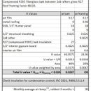
I’m doing an unvented “cathedral” roof on a Mid-Century Modern inspired design. It looks like if I go the U-value route I can keep the roof section considerably thinner. In fact, based on my calculations, using 2×8 rafters @ 24″ o.c., an R30C fiberglass batt compressed into the rafter depth (yielding R27), and a Hunter 3.5″, R18 polyiso panel, I can meet the U-value requirement with a nominal R-value of only 45.
Does that sound about right? Is there really such a big difference in following the U-value vs R-value route?
GBA Detail Library
A collection of one thousand construction details organized by climate and house part






Replies
Jolly,
You are talking about the U-factor alternative path to code compliance. For a fairly thorough discussion of this option, see "Three Code-Approved Tricks for Reducing Insulation Thickness." Here is the link:
https://www.greenbuildingadvisor.com/article/three-code-approved-tricks-for-reducing-insulation-thickness
(Note: see "Trick #3.")
Thanks, Martin.
I wasn't able to make the link work but found it with a quick search. In case anyone else comes across this comment string, here's the link.
https://www.greenbuildingadvisor.com/article/three-code-approved-tricks-for-reducing-insulation-thickness
This was very helpful.
If the cathedral ceiling is a must try not to fill with recessed light fixtures and read this article.
https://www.greenbuildingadvisor.com/article/five-cathedral-ceilings-that-work
Walta
Thanks, Walta. That's a good article and the one it links to as well. I'll be doing a lighting design and certainly won't be using recessed fixtures. I don't much care for them anyway.
The big challenge here is trying to maintain a fairly thin roof section, in line with the Mid-Century Modern aesthetic, especially the way it impacts the appearance of the eaves. That's why I looked into the U-value table, and was a bit surprised at how much the roof requirement, 0.024, differs so much from the R-value. I can't help wondering how the code committee came up with that.
The whole exercise is a bit odd because the 2024 IRC will be going back to the 2018 values.
To my ear it sounds like you are pushing the limits of the code book to build the house with the lowest R value allowed by law. If you take a step back, I do not really think that is what you want to build.
Consider most MCM have wide overhangs could you thin out the bottom of the overhang for looks and still have a thick roof with room for cheap fluffy insulation?
Walta
The final roof insulation stack up will be R18 polyiso and R27 fiberglass, for R45 total. This is pretty near the R49 of the 2018 IRC. And by the way, it looks like the 2024 IRC will be reducing the R-values back to the 2018 levels. So from the U-value standpoint this assembly would be well above the requirement.
I'm also not building in Saskatchewan. Average temperatures in December are around 28f and in August its between 70-80f.
I believe the insulation levels will be adequate and it would be better to put more money into better windows and more labor into air sealing.
I've attached an 'in progress' detail showing the eave treatment, in cause you're curious. I actually did taper the rafters to help reduce the profile.
Jollygreenshortguy,
My calculator says that the U0.024 inverse is R-41.666, so R-45 is a bit more if that is what the local inspector is looking for. You propose squishing R-30 into the bays may work, but I am not sure where you are sourcing the final R-27 value from. Most of my 2x8 are currently running just shy of 7.5 actual inches. You might have a bit of a tussle on your hands getting the ceiling or your polyiso in place.
It may be a moot point though, as you don't say what your stack up actually is. All interior or split some exterior and some interior. Either way, you don't have a viable profile.
You really can't trust having batt insulation against the under side of your roof deck either way. If the polyiso has exterior placement the "R" ratio to inside batt insulation is too low for your CZ. If you are planning on polyiso inside, then the likelyhood of moist air getting into the bays and migrating through the batt insulation are very high, especially at the wall junction.
I will leave it to your engineer to judge whether the 2x8's can handle whatever span you have. I believe many of the MCM homes were built in much milder climates and if not probably were very under insulated. I know the look is seductive, but it would be unwise to build in a roof failure just to get a particular aesthetic result.
I can think of one possible cheat that would get you what you want, but without more info I am a bit loathe to make suggestions. Meantime, don't forget that you will need to calculate the whole roof u-value as noted. The rather wide spacing of the 2x8's will ding your total thermal numbers less than 16" spacing, but mind the bridging losses.
Why do you think his ratio is off? It’s exactly a 40% on exterior which is appropriate for zone 5. Also his image shows his stack up.
onslow - Thanks for your comprehensive comment. It serves as a good check to make sure I've covered all the issues. I believe I have. The local jurisdiction is using IRC 2021. So everything I write here and wrote above is based on that.
My stack up - It's in the image I attached to the original post. But I'm attaching my "in progress" detail here as well. In my original post I listed the items from the top down, exterior air film, metal roofing, polyiso nailbase panel, structural sheathing, rafters, fiberglass insulation, interior ceiling, interior air film. I didn't include elements that weren't relevant to calculating the U-value, such as roofing underlayment. That will be covered, of course, in the relevant details.
Owens-Corning publishes a table with compressed R values for their products. I'll attach it to this. Their R30C insulation is 8.25" thick, and compressed to 7.25" it yields R27.
For the polyiso I'm using Hunter Panel's nailbase. This will be applied above the structural roof sheathing and serve as the base for a metal roof. The structural sheathing itself will be fully taped, as part of the air barrier system. But I didn't mention that in the discussion because it's irrelevant to the U-value question I had.
The R ratio given in the IRC table (covered in the image in my original post) is for R20 impermeable and R60 total, so 40%. With the U-value based insulations of R18 and R27 I maintain the identical ratio. So I'm confident that aspect of the design will work and I don't expect pushback from the building department. I've complied with the ratio in the table, if not the R20 number itself. If they know anything about the reason for the numbers in the table they'll know I'm in line with that.
The ground snow load is 30psf. I've checked the framing. It's based on IRC Table R802.4.1(4), DF-L #2 @ 24" spans 13'2", with an L/240 deflection. My span is 12'5". It's a light roof, 2:12 slope. It's all code but if I decide the L/240 deflection is a bit much I can easily reduce the rafter spacing to 16" with no impact on other elements in the design. Since I've probably been over-conservative in my framing factor (see below) a 16" spacing will probably alright.
It's my understanding that it's strongly advisable, when combining batt insulation with either closed cell spray foam under the sheathing, or as I've done, foam sheets above the structural sheathing, that the batt material should be up tight against the upper surface. By compressing the batt into the slightly shallow rafter space, tight against the underside of the structural sheathing I'm actually improving things on that score.
As far as the total roof U-value it's a simple gable roof with no penetrations other than a plumbing vent or two. So, unlike a wall with headers, double studs... it should have very little additional framing. I've used a framing factor of 80/20. But in further research in the past day it appears that is a very conservative factor for roof framing and I've found references that use 90/10 and even 92/8.
jgsg,
Everything looks good! One small point:
Unless you need the blocking attached to the top plate for structural purposes, I would move it out past the exterior plywood and also angle it to match the roof pitch for a few reasons.
- It allows the batt insulation to extend out to cover the whole top-plate
- It protects the top of the nail-base
- It provides a surface to butt the siding and trim below to
- It eliminates a ledge that from my experience accumulates dirt, and birds love to perch & nest on
- The angle makes the blocking much easier to install. No bevel cuts on the top.
Malcolm, thanks for the tips. You've got some good things to consider there. This project is in a D1 seismic zone. So my hunch is the blocking, as I've shown it, is the simplest way to transfer shear from the roof diaphragm into the walls. I like to try to keep my load paths as direct as possible. Shear nailing from roof sheathing to blocking, and a Simpson A34 between each rafter and the job is done. There are certainly other ways though and I'll look into them. As I mentioned, this detail is 'in progress'. I had not intended to share it and only did so to clarify the roofing assembly.
jolly,
My bad for not looking at the attached build up. In my ratio defense, Mr. Maines has previously said 50% for CZ5, but given your very mild December temps all should be good. Sometimes I forget that not everyone is faced with zero or subzero design points.
If you can extend your exterior CI all the way up to the roof sheathing you will greatly temper the the thermal short you have at the wall top plates and blocking. As drawn you only have R-2 or less directly at the ends of your batts and only R-8 at your top plates. At least as far as any vapor intrusion is concerned. You could encourage condensation here with those values. I have lived in houses that show clear condensation on the drywall at this type of junction.
You are definitely erring on the safe side with an 80/20 framing factor for most roofs. If looking at the simplest framed area above the room, 24" bays will yield around 7% and 16" bays 10% for a 20' wide room. This doesn't cover blocking and other features on the gable side, but using the top side insulation dampens the framing effects.
Happy building.
Thanks! I'll certainly extend the wall insulation up to the underside of the roof sheathing. That will mean a few fussy cuts getting around the rafter tails. But it's definitely worth it.